Batteries & Fuel Cells Module Updates
For users of the Batteries & Fuel Cells Module, COMSOL Multiphysics® version 5.3 includes a new boundary condition for charge-discharge cycling, new boundary conditions for modeling thin layers, as well as new physics interfaces for modeling reacting flow in porous media and chemical species transport in fractures. Browse all of the Batteries & Fuel Cells Module updates in more detail below.
Ion-Exchange Membrane Internal Boundary Condition in the Tertiary Current Distribution, Nernst-Planck Interface
The new Ion-Exchange Membrane boundary node specifies a boundary condition where the flux of ions is continuous, but where the electrolyte potential is discontinuous and is described by a Donnan equilibrium. This condition is typically used in electrochemical cells containing both free electrolytes and ion-exchange membranes, for instance, in dialysis problems. A Donnan potential shift over the interface is calculated automatically from the concentrations of the charge-carrying ion on each side of the interface.
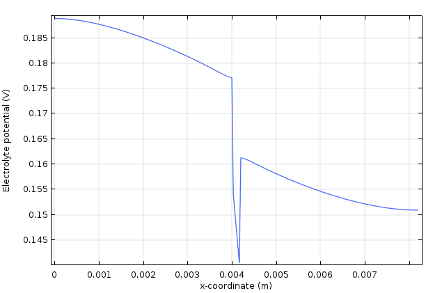 Electrolyte potential in a vananadium redox flow battery showing the potential shifts at the interfaces between the free electrolyte and the ion-exchange membrane.
Application Library path for the updated Vanadium Redox Flow Battery model:
Batteries_&_Fuel_Cells_Module/Flow_Batteries/v_flow_battery
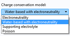
New Charge Conservation Models in the Tertiary Current Distribution, Nernst-Planck Interface
The Tertiary Current Distribution, Nernst-Planck interface now supports four different charge conservation models: electroneutrality, water-based with electroneutrality, supporting electrolyte, and Poisson.
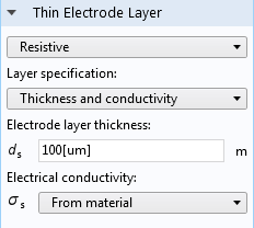
Thin Electrode Layer Functionality
The Thin Electrode Layer feature can be used to model a thin insulating or resistive sheet, located on an internal boundary in an electrode domain. The functionality can be used as an alternative to drawing the actual layer domain in the model geometry, which significantly reduces meshing and solution time, especially in 3D models. A thin electrode layer can be used to model, for instance, a contact impedance between two electronic conductors. The layer may be set to be either insulating or resistive.
Thin Electrolyte Layer
The Thin Electrolyte Layer feature specifies a thin electrolyte layer on an internal boundary between two electrolyte domains. The node can be used as an alternative to drawing the actual layer as a domain in the model geometry in order to significantly reduce meshing and solution time. The condition may be set to either insulating, resistive, or ion-exchange membrane. This feature replaces the Thin Insulating Layer feature in earlier versions.
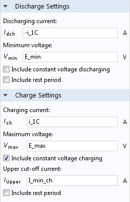
Charge-Discharge Cycling Conditions
You may use the Charge Discharge Cycling boundary condition to specify load cycling in time-dependent simulations, where the switch between charge and discharge depends on the resulting cell voltage (or current). This feature may, for instance, be used for constant-current/constant-voltage (CCCV) cycling in battery simulations. Charge-discharge cycling is now also available as a boundary condition in the Electrode Surface node and as an operation mode in the Single Particle Battery interface.
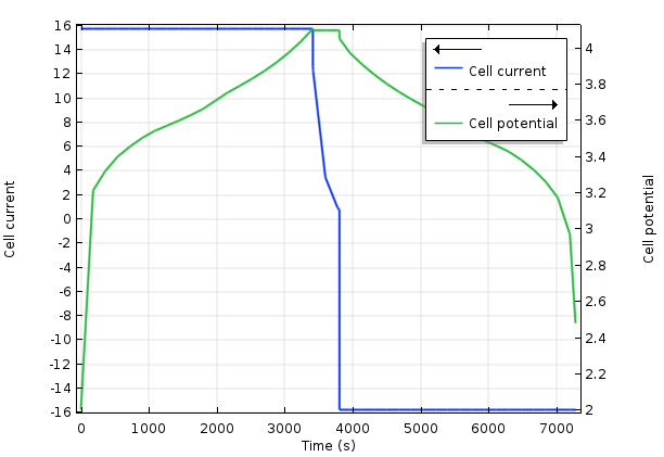
Current and potential during a charge-discharge (constant current-constant voltage) cycle of a lithium-ion battery. From the Batteries & Fuel Cells Module Application Library.
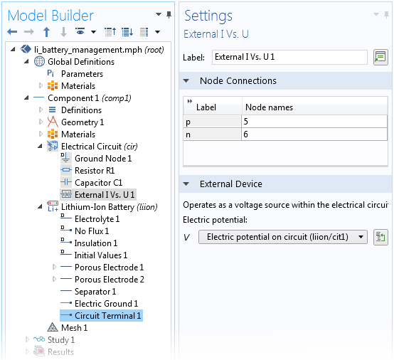
Circuit Terminal Condition
You can use the Circuit Terminal feature on a boundary to specify a coupling to the External I Vs. U node in the Electrical Circuit interface from the AC/DC Module. The Circuit Terminal condition is now also available as a boundary condition in the Electrode Surface node and as an operation mode in the Single Particle Battery interface. This allows you to include high-fidelity battery models in circuit simulations.
New Reacting Flow in Porous Media Interface
Modeling packed beds, monolithic reactors, and other catalytic heterogeneous reactors is substantially simplified with the new Reacting Flow in Porous Media multiphysics interface. This defines the diffusion, convection, migration, and reaction of chemical species for porous media flow, without having to set up separate interfaces and couple them. The multiphysics interface automatically combines all of the couplings and physics interfaces required for the modeling of heterogeneous catalysis together with porous media flow and dilute or concentrated chemical species transport.
As this multiphysics interface complements similar ones for laminar and turbulent flow, you can switch or define new couplings to other types of flow models without having to redefine and set up a new interface for the participating physical phenomena. The Settings window allows you to select the type of flow to be modeled as well as the transport of chemical species, without losing any of the defined material properties or reaction kinetics. This means that you can compare different reactor structures or model flow in both free and porous media in one reactor, even when the two regimes are connected (see image).
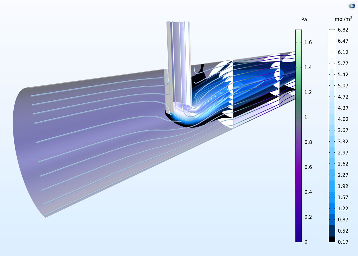
Model of a porous microreactor showing the concentration isosurfaces of a reactant injected through a vertical needle into a free flow containing a second reactant that is then forced through a monolithic catalytic porous media section of the reactor. The model can now be fully defined with the new Reacting Flow in Porous Media multiphysics interface.
Application Library path for an example using the new Reacting Flow in Porous Media interface:
Chemical_Reaction_Engineering_Module/Reactors_with_PorousCatalyst_porous_reactor
New Transport of Diluted Species in Fractures Interface
Fractures have thicknesses that are very small compared to their length and width dimensions. It is often difficult to model the transport of chemical species in such fractures through having to mesh the thickness of the fracture surface, due to the aspect ratios brought about by the large differences in size dimensions. The new Transport of Diluted Species in Fractures interface treats the fracture as a shell, where only the transverse dimensions are meshed as a surface mesh.
The interface allows you to define the average fracture thickness, as well as the porosity in cases where the fracture is considered to be a porous structure. For the transport of the chemical species, the interface allows definition of effective diffusivity models to include the effects of porosity. Convective transport can be coupled to a Thin-Film Flow interface or through including your own equations to define fluid flow through the fracture. Additionally, chemical reactions can be defined to occur within the fractures, at its surfaces, or in a porous medium that encompasses the fracture.
 Transport of diluted species along a slightly curved fracture surface. The curved surface consists of an imprinted tortuous path through the surface where flow and chemical species transport occur.
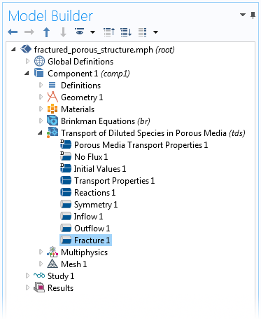
Fracture Surfaces in the Transport of Diluted Species in Porous Media Interface
In cases where transport occurs in a fractured, porous 3D structure, the new Fracture boundary condition lets you model transport in the thin fractures without having to mesh them as 3D entities. The Fracture boundary condition is included in the Transport of Diluted Species in Porous Media interface (see image) and has the same settings as in the Transport of Diluted Species in Fractures interface (described above). Fluid flow and chemical species transport are seamlessly coupled between a 3D porous media structure and fluid flow and chemical species transport in a fracture.
The image below shows the concentration field in a porous reactor model. In the model, a twisted fracture "leaks" reactants deeper into the porous catalyst, from left to right, at a faster rate than the transport through the porous media. This is because the fracture surface has a much higher average porosity compared to the surrounding porous catalyst, which gives a higher mass transport rate.
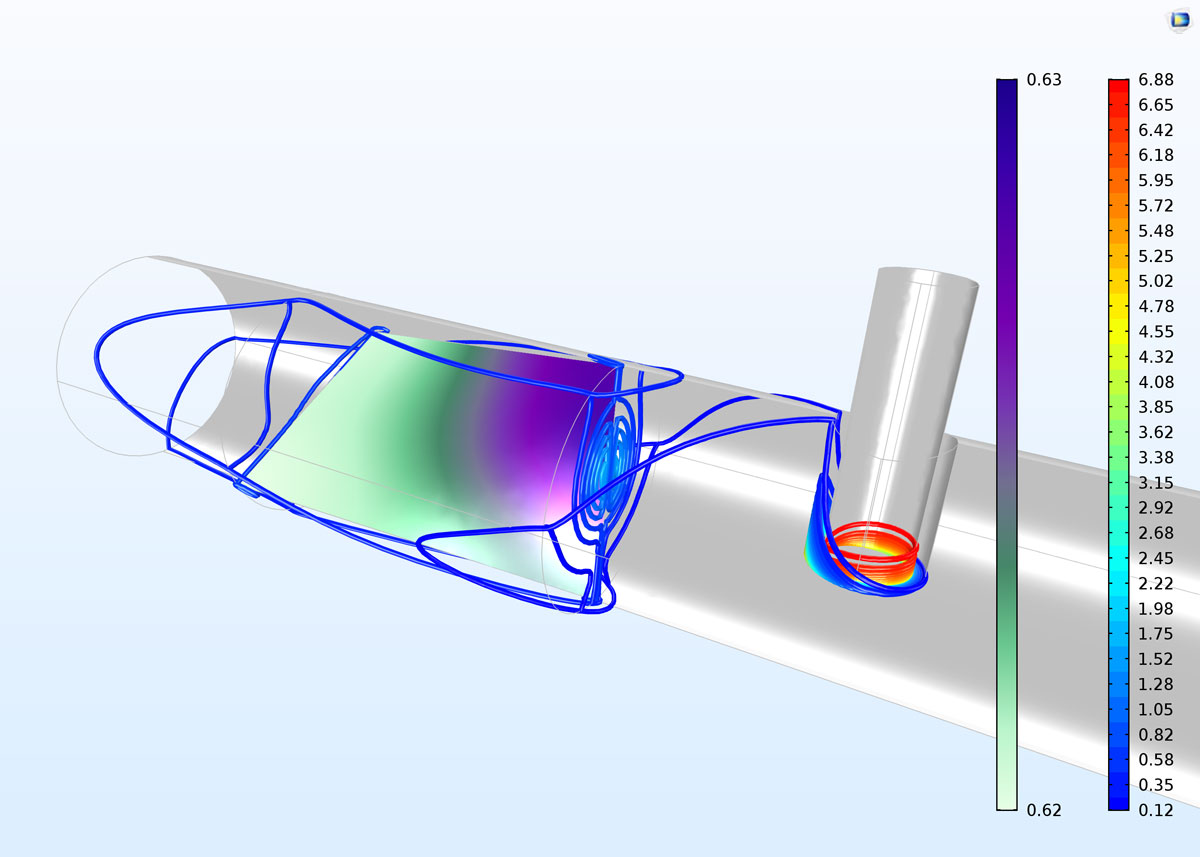 Concentration contours through the 3D reactor and surface concentration in the fracture surface. The higher mass transport rate in the fracture surface gives a larger penetration (from right to left) of unreacted species into the catalyst bed. We can see that the change in concentration from right to left is very small in the fracture surface (from 0.63 to 0.62 mol/m3).
New Electrophoretic Transport Interface
The new Electrophoretic Transport interface can be used to investigate the transport of weak acids, bases, and ampholytes in aqueous solvents. The physics interface is typically used to model various electrophoresis modes, such as zone electrophoresis, isothachophoresis, isoelectric focusing, and moving boundary electrophoresis, but is applicable to any aqueous system involving multiple acid-base equilibria.