Geometry Updates
The geometry improvements in COMSOL Multiphysics® version 5.3 are quite extensive. In this version, you can specify local coordinate systems for easier geometry building and physics definition operations, and the new Remove Details feature automatically creates virtual geometry operations for you. In addition, some geometry operations are now much faster and use less memory. See all of the geometry updates below.
Use Coordinate Systems Defined by Work Planes When Creating Geometries
Before the new version of COMSOL Multiphysics®, when building your geometries, you had to define the positions and orientations of primitive objects using the standard global coordinate system. Now, you can work in a local coordinate system when editing the settings of a primitive or transform feature that is used to build your geometry. You can do this by first creating a work plane, which defines the local coordinate system in which you would like to work. New primitives that are then added to your geometry use this new local coordinate system, so you can more easily specify the primitive's position and orientation. To use this new functionality, you choose the work plane in the Coordinate System section in the Settings window. Then, the work plane and its local coordinate system axes — xw, yw, and zw — appear in the Graphics window.
Use Coordinate Systems Defined by Geometry Orientations
Sometimes, definitions of physical equations and properties are defined using the directional vectors of the coordinate system to which they belong. Yet, if the geometry of the modeling domain does not align easily with the global coordinate system, it can be difficult to define the physical equations and properties that are dependent on the coordinates' directions. Examples of this are the definitions of anisotropic materials' physical parameters, which are dependent on their orientations.
Now, you can use a local coordinate system that coincides with the positioning and alignment of a geometric entity to define these physical equations and properties. In the Coordinate Systems menu of the Definitions node, you can choose a new coordinate system type: System from Geometry. This feature creates a coordinate system corresponding to a chosen work plane, thereby making it easy to create a coordinate system for use in physics that is aligned to certain geometric entities. Physical equations can now be defined using the new coordinate axes xw, yw, and zw. In addition, a Base Vector System, Rotated System, Cylindrical System, and Spherical System can also be defined relative to a work plane's local coordinate system.
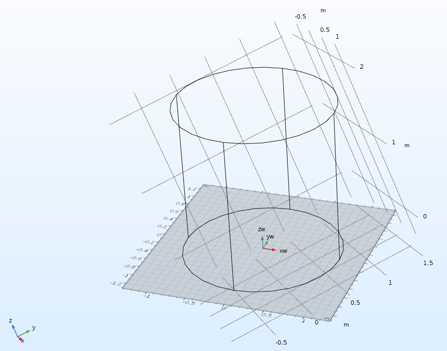 A work plane coincides with the bottom face of a cylinder that is at an angle to the global coordinate system. A local coordinate system has been aligned with this work plane. Physical equations and properties can be specified in this coordinate system.
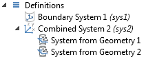
Use Combined Coordinate Systems Defined by Different Geometry Orientations
Defining physics and properties for multiple geometric domains can be difficult when the orientation of the domains' geometric entities does not align. Rather than manipulating your equations to take this into account, the COMSOL Multiphysics® software can do this for you through combined coordinate systems.
In a Combined System node under the Definitions node (see image), the coordinate system can be specified according to the different orientations of the geometric entities in different domains of your geometry. Using the combined coordinate system, you can then define physical equations and properties according to the orientation of the respective domain.
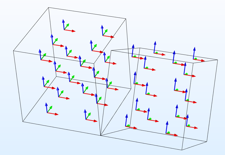
Two domains with different orientations are connected. The local coordinate system for each domain can be aligned to the respective geometry's orientation and position by using the System from Geometry feature from a Face parallel work plane.
Automatically Remove Geometric Details with Virtual Geometry Operations
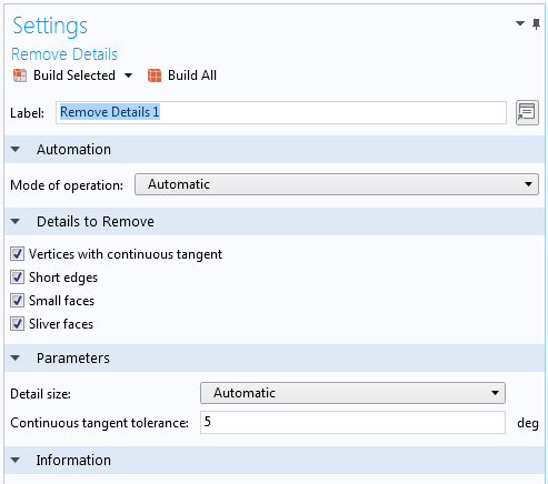
A new 3D geometry operation, Remove Details, has been introduced in order to preprocess your CAD geometries for more successful meshing. This is particularly useful for geometries with small geometric details, which can lead to large meshes of poor quality if they are not handled in a meaningful way.
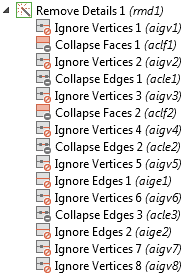
The operation automatically removes short edges and small and sliver (narrow) faces from geometries. The Remove Details operation has two modes: Automatic and Manual. When you remove details in Automatic mode, the operation generates a sequence of virtual operation nodes that you can inspect and edit by switching to Manual mode.
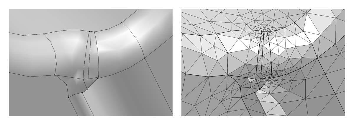 A CAD geometry containing short edges, small faces, and sliver faces (left) results in the corresponding mesh (right).

After rebuilding the geometry with the Remove Details operation (left), a much better mesh results (right).
Application Library path for an example using the Remove Details operation: ECAD_Module/Tutorials/pcb_import
Enhancements in Extrusion Operations
The operation that extrudes faces to 3D objects now has more flexibility. By selecting Vertices to extrude to in the Distances section of the Extrude Settings window, you can extrude a face until it reaches an existing object, which is specified by one or more vertices. To create 3D objects that are symmetrical around a plane, you can select Distances from plane in the Distances section in the Extrude Settings window. This now provides the possibility to extrude a plane in two opposite directions using positive and negative values in the appropriate edit fields.
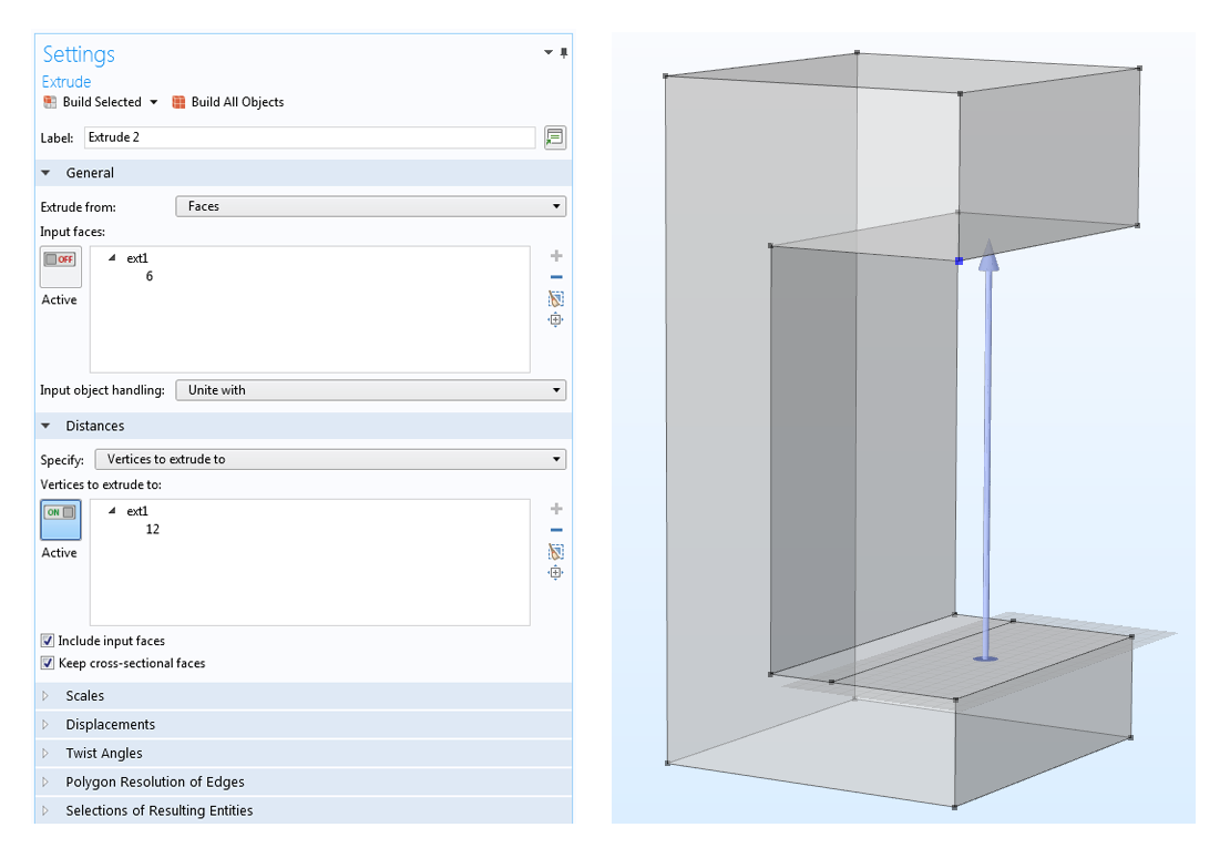
The Extrude Settings window (left), where an input face is allowed to extrude to a specified vertex. The Graphics window (right) shows the extrusion distance using an arrow.
Enhancements in Selection of Entities Using Cylinder and Disk Selections
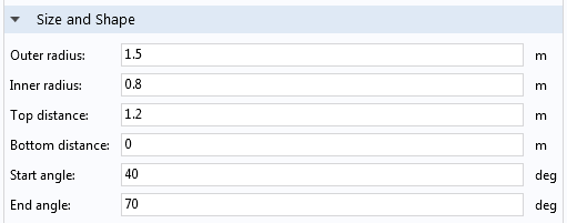
Useful in complicated arrays with many components, new settings allow for easier selections of entities, such as boundaries, which can then be used for further operations. In 3D, you can select sections of a geometry by surrounding them with parts of a cylinder. The Cylinder selection operation in 3D, which can be found under the Geometry and Definitions nodes, now allows for the definition of an inner and outer radius as well as an angle that the Cylinder selection would sweep through. This describes a sector that can capture a selection of entities within the overall object. Similar operations can be performed in 2D using the Disk selection operation (previously called the Ball selection operation).
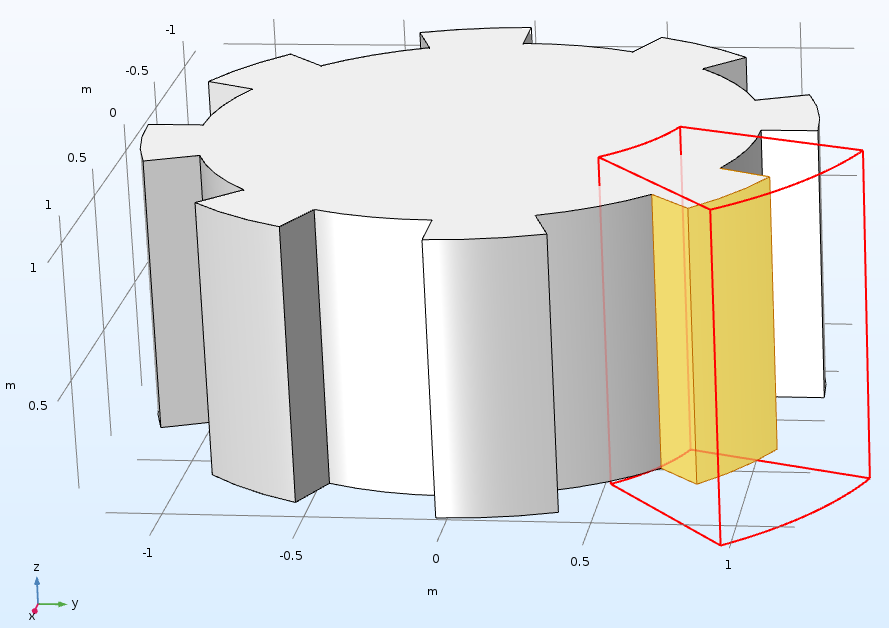
A Cylinder selection that selects the boundaries inside a sector of a hollow cylinder.
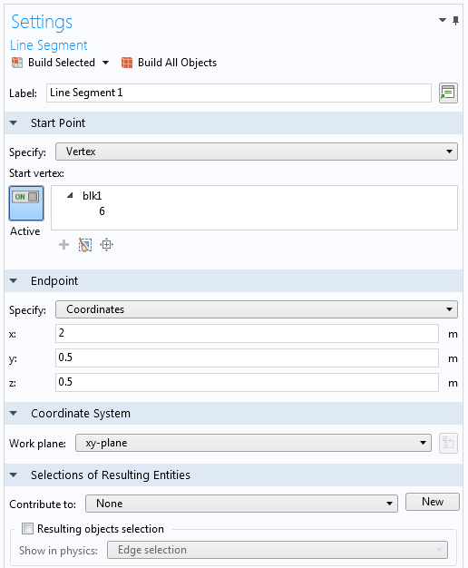
Line Segment
A new geometry primitive for 2D and 3D operations, Line Segment, has been introduced in COMSOL Multiphysics® version 5.3. The start point and the endpoint can be specified either by selecting a vertex or entering coordinates into the Line Segment Settings window.
Generating 2D Selections from 3D Selections Using Cross Sections
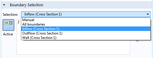
Improvements have been made that enable you to more easily specify selections in COMSOL Multiphysics®. In particular, it is now straightforward to generate 2D selections from selections that have already been specified in 3D. This is useful, for example, if you want to create a 2D axisymmetric geometry from an imported 3D geometry. Assuming that the CAD software has defined 3D boundary selections consisting of the inflow, outflow, and wall for the modeling domain, these entities will now be available as 2D boundary selections when defining the physics for the axisymmetric model.
The new functionality for creating 2D selections is accessed through the Cross Section feature and is made available by selecting the check box Selections from 3D in this feature's Settings window. The operation will then create a 2D selection from each 3D selection specified in the geometry sequence that precedes the work plane node. A 2D selection is constructed by the intersection between the work plane and 3D selection. With this functionality, a 3D domain selection would create a domain selection in 2D, while a 3D boundary selection would create a boundary selection in 2D.
Geometry Part Variants
If you make your own library of geometry parts, you can now store several variants of a part in a single MPH-file. Each variant is defined by a Geometry part node under the Global definitions node, where you should select the Show as variant in part library check box in the Settings window. Typically, one of the variants contains the main geometric sequence for building the part, while the other ones are wrappers that contain an instance of the "worker" variant of the part. When you load a part that contains several variants, a dialog box appears where you can choose which variant to use for your model.