Electrodeposition Module Updates
For users of the Electrodeposition Module, COMSOL Multiphysics® version 5.3 brings a new Current Distribution, Boundary Elements interface, a new Electrophoretic Flow interface, and new features in the Tertiary Current Distribution, Nernst-Planck interface. See all of the Electrodeposition Module updates in more detail below.
Current Distribution, Boundary Elements Interface
The Current Distribution, Boundary Elements interface can be used for solving primary and secondary current distribution problems on geometries based on edge (beam or wire) and surface elements. The interface uses a boundary element method (BEM) formulation to solve for the charge transfer equation in an electrolyte of constant conductivity, where the electrodes are specified on boundaries or as tubes with a given radius around the edges. You typically use this interface in order to reduce the meshing and solver time for large geometries, where a significant part of the geometry can be approximated as tubes along edges.
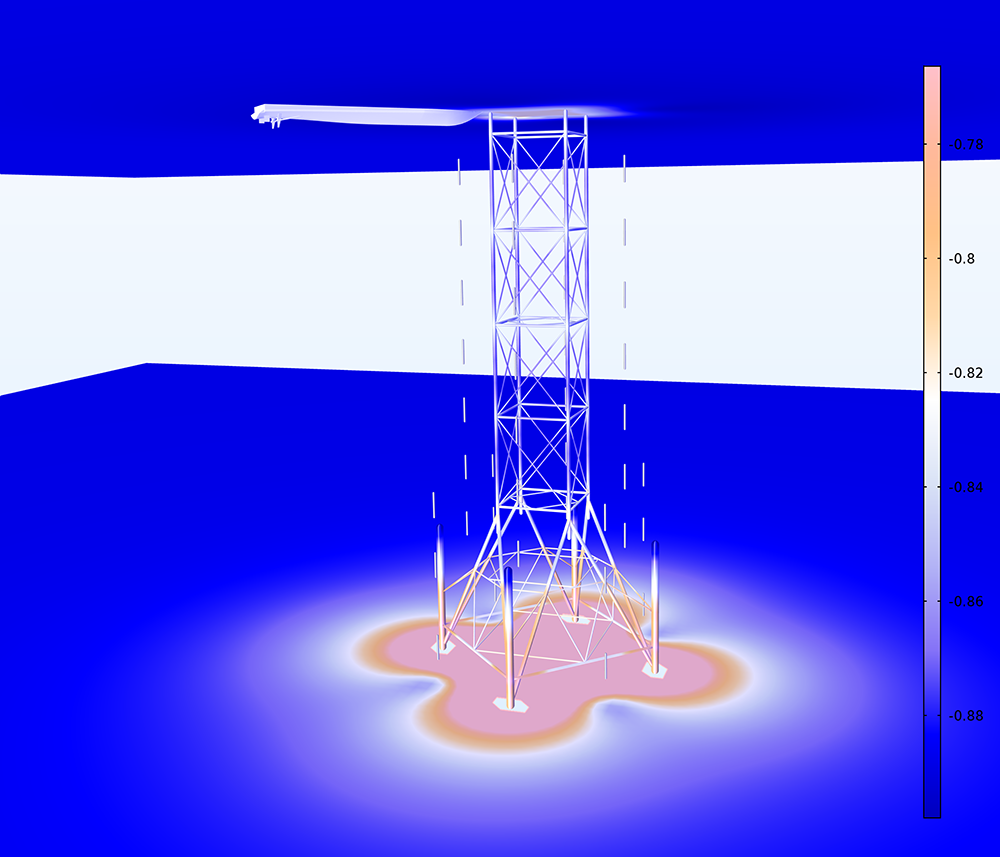
A ship is anchored close to an oil platform. The ship hull is subjected to the electric field from the cathodic corrosion system. The figure to the left shows an insulated hull, for example insulated by a thick paint.
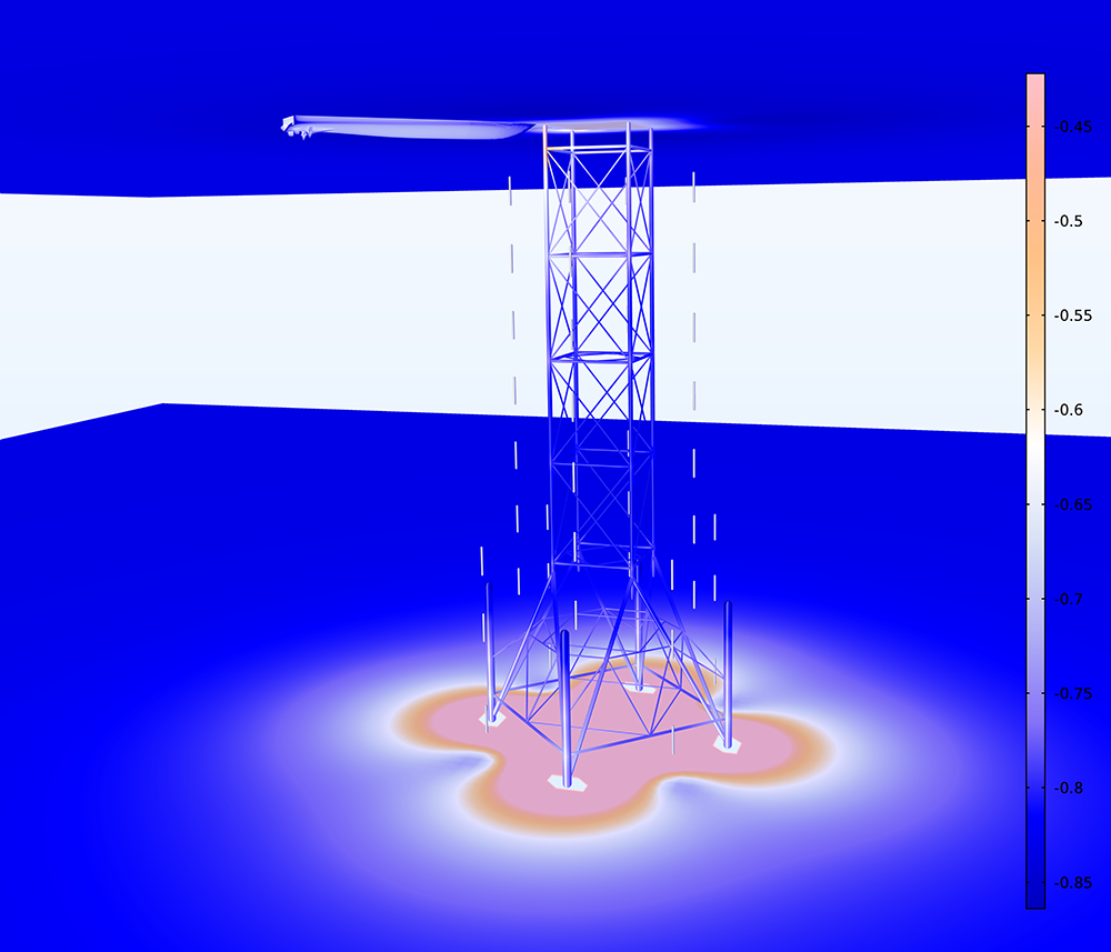
A ship is anchored close to an oil platform. The ship hull is subjected to the electric field from the cathodic corrosion system. The figure here shows a ship where parts are of the hull are bare steel, where the hull may work as a bipolar electrode. Here, the stem works as an anode while the stern works as a cathode. The oil rig structure close to the ship is cathodically polarized. A fraction of the impressed current goes from the sacrificial anodes (rods) through seawater, into the ship hull, out of the ship hull, through seawater and then into the oil rig structure.
Ion-Exchange Membrane Internal Boundary Condition in the Tertiary Current Distribution, Nernst-Planck Interface
The new Ion-Exchange Membrane boundary node specifies a boundary condition where the flux of ions is continuous, but where the electrolyte potential is discontinuous and is described by a Donnan equilibrium. This condition is typically used in electrochemical cells containing both free electrolytes and ion-exchange membranes, for instance, in dialysis problems. A Donnan potential shift over the interface is calculated automatically from the concentrations of the charge-carrying ion on each side of the interface.
 Electrolyte potential in a vananadium redox flow battery showing the potential shifts at the interfaces between the free electrolyte and the ion-exchange membrane.
Application Library path for the updated Vanadium Redox Flow Battery model:
Batteries_&_Fuel_Cells_Module/Flow_Batteries/v_flow_battery
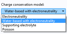
New Charge Conservation Models in the Tertiary Current Distribution, Nernst-Planck Interface
The Tertiary Current Distribution, Nernst-Planck interface now supports four different charge conservation models: electroneutrality, water-based with electroneutrality, supporting electrolyte, and Poisson.
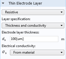
Thin Electrode Layer Functionality
The Thin Electrode Layer feature can be used to model a thin insulating or resistive sheet, located on an internal boundary in an electrode domain. The functionality can be used as an alternative to drawing the actual layer domain in the model geometry, which significantly reduces meshing and solution time, especially in 3D models. A thin electrode layer can be used to model, for instance, a contact impedance between two electronic conductors. The layer may be set to be either insulating or resistive.
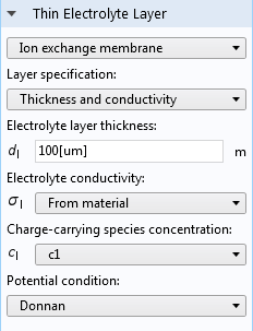
Thin Electrolyte Layer
The Thin Electrolyte Layer feature specifies a thin electrolyte layer on an internal boundary between two electrolyte domains. The node can be used as an alternative to drawing the actual layer as a domain in the model geometry in order to significantly reduce meshing and solution time. The condition may be set to either insulating, resistive, or ion-exchange membrane. This feature replaces the Thin Insulating Layer feature in earlier versions.
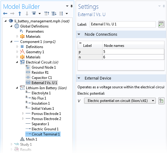
Circuit Terminal Condition
You can use the Circuit Terminal feature on a boundary to specify a coupling to the External I Vs. U node in the Electrical Circuit interface from the AC/DC Module. The Circuit Terminal condition is now also available as a boundary condition in the Electrode Surface node and as an operation mode in the Single Particle Battery interface. This allows you to include high-fidelity battery models in circuit simulations.
New Electrophoretic Transport Interface
The new Electrophoretic Transport interface can be used to investigate the transport of weak acids, bases, and ampholytes in aqueous solvents. The physics interface is typically used to model various electrophoresis modes, such as zone electrophoresis, isothachophoresis, isoelectric focusing, and moving boundary electrophoresis, but is applicable to any aqueous system involving multiple acid-base equilibria.