Fatigue Module

Analyze the Fatigue of Structural Components

The Fatigue Module, an add-on to the Structural Mechanics Module, is used for performing fatigue analyses in the COMSOL Multiphysics® environment when structures are subjected to repeated loading and unloading. These analyses can be simulated in solid bodies, plates, shells, multibody systems, applications involving thermal stress and deformation, and even piezoelectric devices.

The capabilities within the Fatigue Module include, but are not limited to, the classical stress- and strain-based and stress- and strain-life models that are suitable for evaluating the high-cycle fatigue (HCF) and low-cycle fatigue (LCF) regimes. The Fatigue Module can also be combined with other modules in the COMSOL® product suite to further expand its multiphysics capabilities, such as modeling thermal expansion or full elastoplastic fatigue.

Contact COMSOL
A model showing the cycle to failure in the Dipole Dark color table.

Identifying Load Cycles to Determine the Fatigue Model

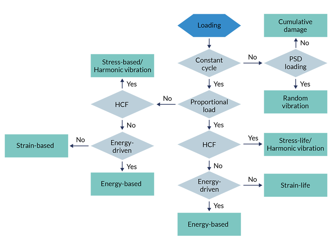
Before running a fatigue analysis, you need to determine which fatigue model accurately reflects your case. You may know which fatigue model to use based on prior knowledge from previous cases. If not, you can decide on a model based on the loading conditions and expected fatigue failure. Generally speaking, load cycles can be divided into the following cases: proportional, nonproportional, and variable amplitude loads.

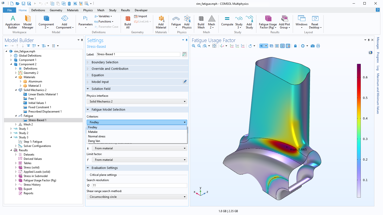
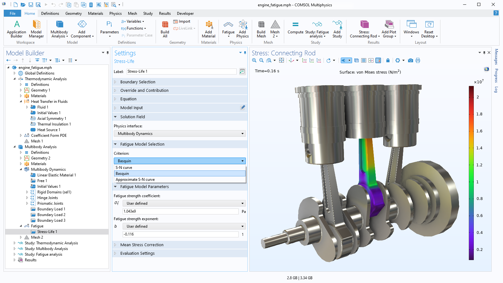
In proportional loading, the orientation of the principal stresses and strains does not change during the load cycle; for HCF, a stress-life model is used and for LCF, a strain-life model. For nonproportional loading, the directions of principal stresses and strains vary: for HCF, a stress-based model is used and for LCF, a strain-based model is used. In some cases, the stress or strain alone is not sufficient for characterizing the fatigue properties, and, in that case, energy-based models can be used.

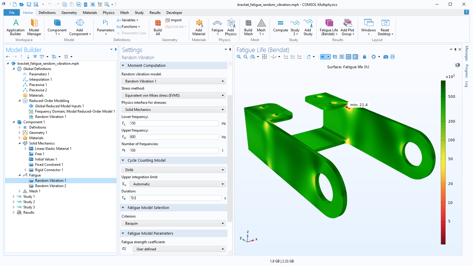
For variable amplitude loading, where there is not a constant cycle, the entire load history (or a sufficiently representative portion) is considered, in which case you would use a cumulative damage fatigue model. Lastly, there is a random vibration fatigue modeling option that uses power spectral density (PSD) loading as an input.

Running a Fatigue Analysis in COMSOL Multiphysics®

Once you have identified the type of load cycle and determined the appropriate fatigue model, you are ready to set up and run a fatigue analysis in COMSOL Multiphysics®. As input, the Fatigue Module takes the results from a structural mechanics analysis, where the stresses and strains have been computed. The results on which the fatigue evaluation is based can come from the following types of analyses:

  • Stationary
    • Load cases
    • Parametric sweeps
  • Time dependent
  • Frequency domain
  • Random vibration

The results of your fatigue analysis depend on the fatigue model selected. They will either be a lifetime prediction in terms of the number of cycles to fatigue or a usage factor that will tell you how close the given load cycle is to the fatigue limit. Energy-based analyses will give a lifetime prediction and a dissipated fatigue energy density.

Features and Functionality in the Fatigue Module

Find various types of fatigue models for evaluating the structural integrity of components subjected to repetitive loads.

A close-up view of the Stress-Based settings and a rim model in the Graphics window.

Stress- and Strain-Based Models

For multiaxial cases, many of the most popular fatigue criteria use a critical plane approach for calculating fatigue. This approach entails identifying the plane on which some stress or strain expression is maximized. Different fatigue models use different stress or strain expressions, and the Fatigue Module features both stress- and strain-based models.

In the high-cycle fatigue regime, where plastic strains are negligible, stress-based models — Findley, Normal stress, Matake, or Dang Van — are used to calculate a fatigue usage factor that is compared to the fatigue limit.

In situations where plastic strains can no longer be neglected, strain-based models are available. They use strain expressions or expressions that combine stress and strain to calculate the number of cycles to fatigue failure. The Smith-Watson-Topper (SWT), Fatemi-Socie, and Wang-Brown models are typically relevant in low-cycle fatigue situations.

A close-up view of the Model Builder with the Cumulative Damage node highlighted and a thin-walled frame model in the Graphics window.

Cumulative Damage Model

In cases where the load cycle is not constant, the loading is described by a complete stress history rather than a single constant stress cycle. You can use the Cumulative Damage feature to evaluate fatigue of a structure that is subjected to either variable loads or "random" loading, where the corresponding stresses are binned using rainflow counting. Once the stress distribution is known, the Palmgren–Miner linear damage rule is used to calculate cumulative damage using an S-N curve. The results are a usage factor, which tells you how close to the fatigue limit the load cycle is; counted stress cycles showing the stress level distribution of the applied load; and the relative usage factor showing the contribution to the overall fatigue usage from each stress level. Matrix histogram plots can be used to visualize the counted stress cycles and the relative fatigue usage.

A close-up view of the Random Vibration settings and a bracket model in the Graphics window.

Vibration Fatigue

When a structure undergoes vibrations, it can lead to fatigue. Vibrations can be broadly categorized into deterministic or random processes. The Fatigue Module includes features for assessing fatigue accordingly.

Harmonic vibration fatigue analysis is based on the results from a frequency-domain sweep. Here, you additionally specify the frequency history as, for example, the time spent at each frequency or a frequency time rate of change. The result is a usage factor, which tells you how much of the fatigue life has been consumed by the cycles in the frequency sweep.

Random vibration fatigue analysis is based on results from a random vibration analysis where the loading is represented by PSD. The Random Vibration feature in the Fatigue interface can be used to define any linear stress measure and provides several different results that emanate from the PSD response. These help you evaluate the structure with regard to the risk for fatigue failure.

A close-up view of the Stress-Life settings and an engine model in the Graphics window.

Stress- and Strain-Life Models

The stress-life and the strain-life models in the Fatigue Module provide a collection of methods where the stress or the strain amplitude relates to the fatigue lifetime via a fatigue curve. These models are suitable for proportional loading when, for example, a single load oscillates between two values. To simulate high-cycle fatigue, the module includes the S-N curve, Basquin, and an Approximate S-N curve stress-life models. For the low-fatigue regime, the E-N curve, Coffin-Manson, and Combined Basquin and Coffin-Manson strain-life models are available.

A close-up view of the Model Builder with the Energy-Based node highlighted and a surface mount resistor model in the Graphics window.

Energy-Based Models

In the Fatigue Module, two energy-based models are included: Morrow and Darveaux, which are used to combine the effect of stress and strain into energy that is released or dissipated during a load cycle.

These models are typically suitable in applications involving nonlinear materials in the low-cycle fatigue regime. Since the energy can be calculated in different ways, these models can be used in both proportionally and nonproportionally loaded applications.

The energy-based models depend on the dissipated energy. Energy dissipation means that the energy is consumed by the material and cannot be restored. This behavior is exhibited by inelastic materials and can be modeled by combining the Fatigue Module with the Nonlinear Structural Materials Module or Geomechanics Module.

A close-up view of the Thermal Expansion settings and a circuit board model in the Graphics window.

Multiphysics for Extended Analyses

Material expansions or contractions due to changes in temperature introduce stress concentrations and strain accumulations that can lead to failure. Thermal fatigue failure can be evaluated using several fatigue models. For nonlinear materials, this includes the Coffin-Manson model and the energy-based Morrow and Darveaux relations. In addition to the available options for inelastic strains or dissipated energies, the fatigue evaluation models can also be modified by the user to evaluate strain or energy expressions when calculating fatigue.

You can use the Neuber's rule and Hoffmann–Seeger method to approximate the effect of plasticity in a quick linear elastic simulation. When combined with the Nonlinear Structural Materials Module, it is possible to consider a full elastoplastic fatigue cycle.

To compute the risk of fatigue in multibody systems and solid rotors, the Fatigue Module can be combined with the Multibody Dynamics Module and Rotordynamics Module, respectively.

Every business and every simulation need is different.

In order to fully evaluate whether or not the COMSOL Multiphysics® software will meet your requirements, you need to contact us. By talking to one of our sales representatives, you will get personalized recommendations and fully documented examples to help you get the most out of your evaluation and guide you to choose the best license option to suit your needs.

Just click on the "Contact COMSOL" button, fill in your contact details and any specific comments or questions, and submit. You will receive a response from a sales representative within one business day.

Next Step

Request a Software Demonstration