support@comsol.com
Geometry Updates
COMSOL Multiphysics® version 6.2 introduces the ability to create parameters from certain geometric measurements and brings improvements to the Sweep operation. Read more about these updates below.
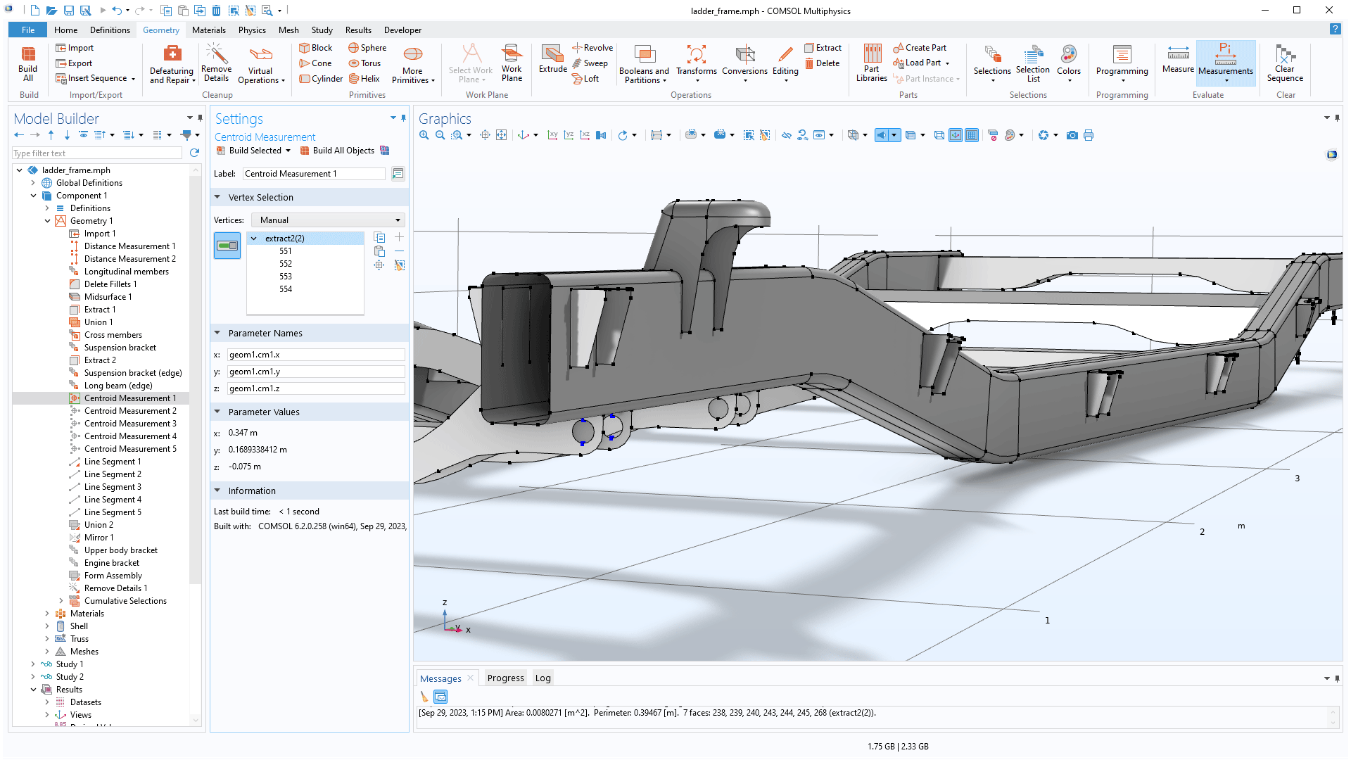
Parameterizing Models Using the New Measurement Parameters
It is now possible to create parameters for the distance between entities or for the average coordinates of a selection of vertices using the new Distance Measurement and Centroid Measurement features, respectively. The parameters can be used in downstream geometry construction and elsewhere in the Model Builder, which makes it easier to parameterize physics settings based on the geometry. This can simplify the workflow when building simulation apps. You can use these new features in the following models:
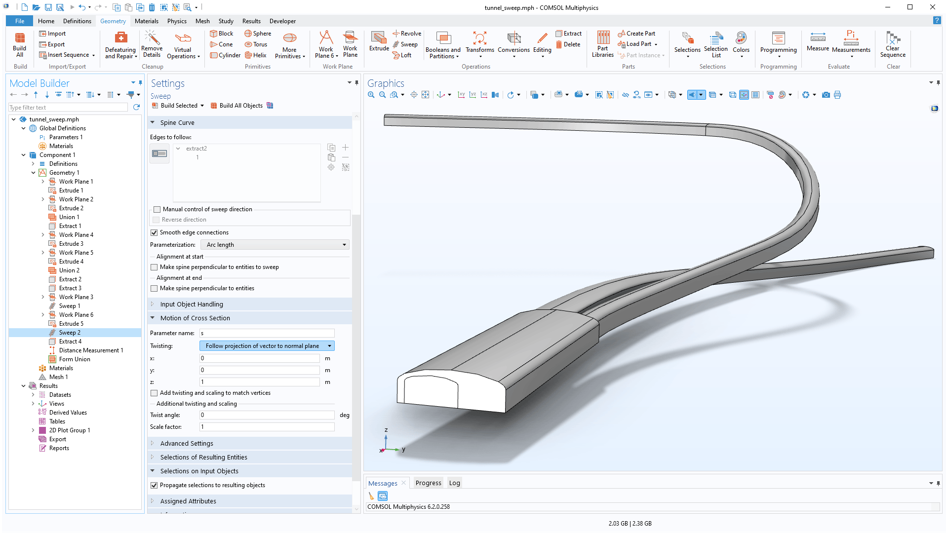
Better Control of Twisting Along a Sweep
The Sweep operation has been improved with better control of the cross section's twisting by specifying a direction vector to follow. This makes it easy to create a tunnel where the floor has a slope only in the sweep direction, for example. It is also possible to sweep points and edges and to align the cross section to an existing object at the end of the spine curve.
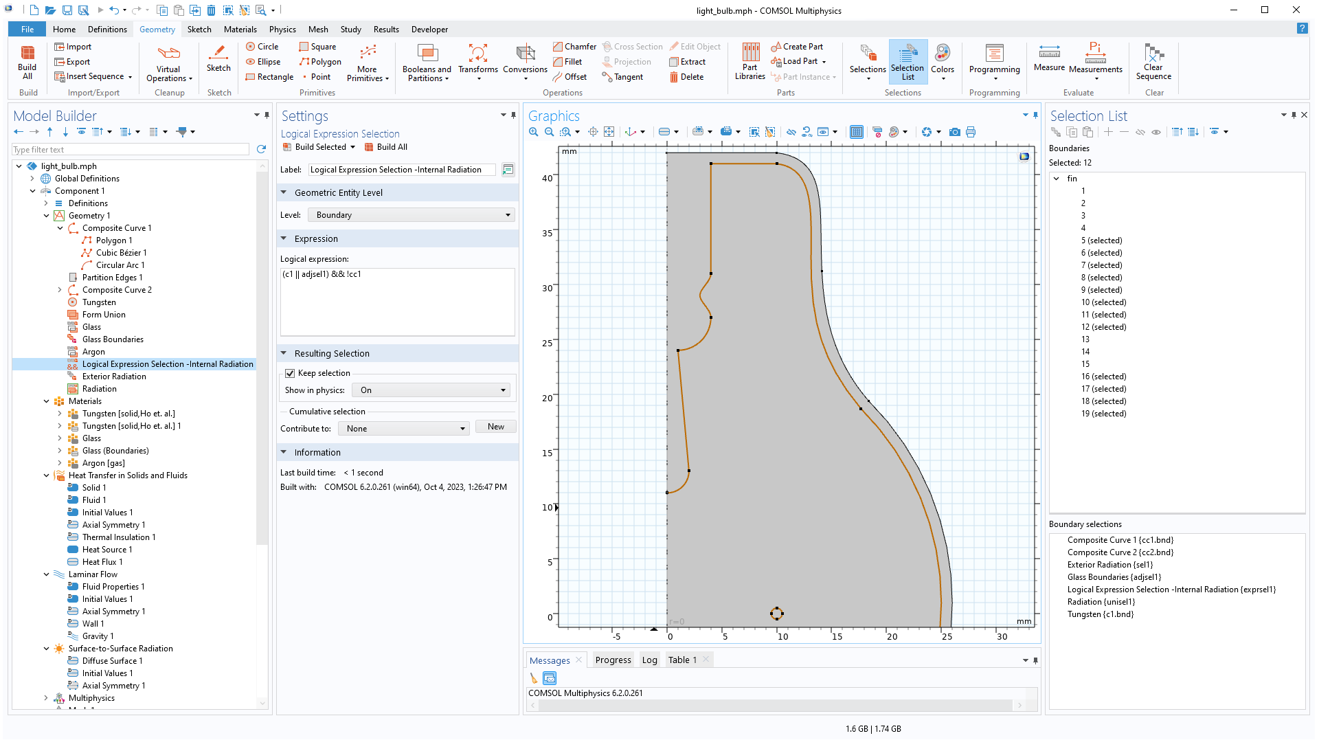
Logical Expression Selection and Quick Access to the Selection List
A Logical Expression Selection feature can be added to the geometry sequence to use a logical expression that quickly combines selections. For example, the expression (sel1||sel2)&&!sel3 means the union of the sel1 and sel2 selections and the subtraction of the sel3 selection. There is now a Selection List button on the Geometry, Mesh, and Definitions ribbon tabs that opens the Selection List window, where all named selections in the model can be viewed and there is an option to create new selections.