Finite Element Analysis of Planar Microcoil Based Induction-balance Magnetic MEMS Sensor
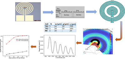
Two transmitting planar microcoils (TX1, TX2) and one receiving microcoil (RX) are employed as shown in Fig.1 formed in induction-balance configuration. RX-Coil is positioned in such a way to achieve primary field suppression in RX-Coil’s region. Meaning, a magnetic cavity is created in the region of receiving coil by concentric placement of two transmitting coils in which exciting currents of equal magnitude are applied in opposing directions. The sensor geometry is built using 2D axi-symmetric modeling in the COMSOL Multiphysics® environment is shown in Fig.2(b). AC/DC module is used to perform the simulations. Coil based physics modules are inserted to model the characteristics of the transmitting and receiving microcoils. Laminar flow physics is used to model the flow of microbead solution above the sensor surface. Physics-based meshing is used with a fine meshing. Density and dynamic viscosity values of the magnetic particle’s solution are set under the laminar flow physics module using the default values from the inbuilt material library. Boundary conditions: At all boundaries between the microcoils and air interface, normal component of magnetic field (Bz) and tangential component of electric field (Er) are continuous. Thus, at the boundary, Er is equal to zero. As normal component of magnetic field intensity vanishes within the conductors, Bz is zero at the boundary. Thus, the tangential electric field and normal magnetic field must be equal to zero at the boundary between coil and air. Results: The FEA results are used to examine the effect of magnetic microbeads on the microcoil sensor as shown in Fig.4. The resultant magnetic field distribution in the magnetic sensor due to input DC excitation of 100µA is shown in Fig.3(a). The observed magnetic flux density is of the order of micro-Tesla at the interface of microparticle array and exciting coils. Magnetic beads near to the inner coil turns of the transmitting coils are magnetised to higher values than those near to the outer turns. The magnetisation acquired are of the order of 50A/m, much lower than the saturation magnetization of the microbeads. Saturation levels are of the order of kA/m for iron oxide microbeads. Current in the RX coil is simulated by applying the microparticle solution over the coil surface which approximately contains ten microparticles. Input currents are varied from 10µA to 500µA, and the resultant current in the sensing coil (RX coil) is studied through simulations for each case. As shown in Fig.3(b), the presence of microparticles causes a modulation of induced current in the RX coil, which is modulated by more than two orders of magnitude to few-microamperes with the application of magnetic microparticles of 50µL volume. The performance comparison of various planar coil sensors indicates that the proposed induction balance sensor showcases a good detection sensitivity which is as small as ten micro particles and better than that of the other planar coil sensors under consideration. Further, the simulated structure is fabrication and characterized which only requires a single metal level lithography, which demonstrates the capability of concept development in COMSOL Multiphysics® to realization.