

Wireless systems are growing increasingly thinner and more advanced. In order to keep this trend going, engineers must consider how to optimize the designs of the components that make up data transmission systems. One such component is the spiral resonator, which allows the system to communicate properly by filtering out unwanted frequencies and letting the appropriate ones through. Spiral resonator filter design can be analyzed and optimized using simulation software, as seen in a recent story from AltaSim Technologies.

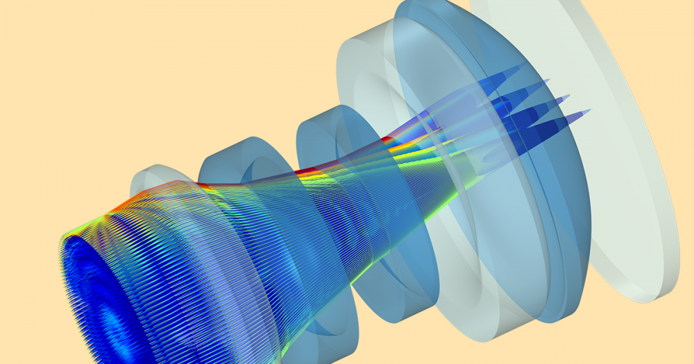
The electric field of a fractal spiral resonator filter.
Band-Stop Filters That Fit in Compact Systems
With modern-day expectations of smaller and more advanced data transmission systems, transmitters and receivers end up within close proximity of each other inside the device. In order for this to work, the systems need to contain band-stop filters — resonator filters that reject incoming frequencies of some predetermined passband (a specific frequency range).
Conventionally, resonator filters have been constructed as rings, but to further accommodate shrinking sizes of systems, they are taking on a spiral shape. By design, spiral resonator filters are much smaller than ring resonators, and you could fit several of them on a single printed circuit board. In order to understand and optimize their performance, we can look to the work of AltaSim Technologies, a COMSOL Certified Consultant.
AltaSim Analyzes Resonator Filter Design
AltaSim Technologies ran simulations of two different types of band-stop spiral resonator filters using COMSOL Multiphysics. The main goal was to determine how well these filters attenuate specific frequencies, by analyzing their frequency response and selectivity. The computational data was then compared with real-life experiments for validation.

|

|
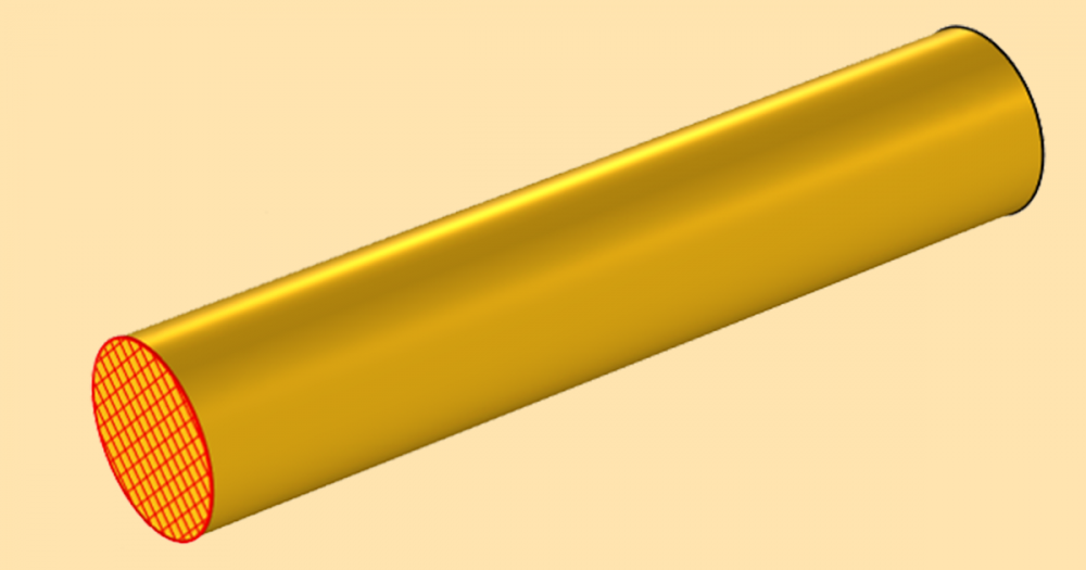
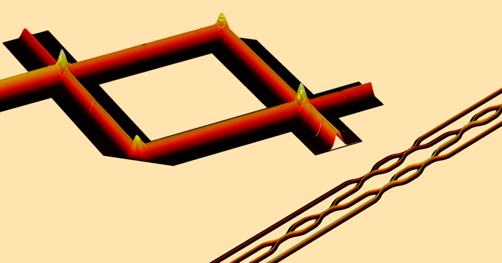
| Microstrip spiral resonator geometry. | Fractal spiral resonator geometry. |
The first model included spiral resonators on a compact microstrip filter. This kind of filter involves etching rectangular spiral resonators on the center line of a microstrip (above, left). Through computational analyses, AltaSim found that the 7.2 GHz frequency resonator exhibited low insertion losses, a sharp cutoff over the desired passband, and overall high performance. For the second simulation, they used the geometry of a fractal spiral resonator developed by Palandöken & Henke. The fractal spiral resonator is made up of two unit cells of electrically small, magnetic metamaterials. These are anti-symmetrically connected along the feeding line via two concentric Hilbert fractal curves, as seen above to the right. Via a reflection and transmission analysis, they found that at an operating frequency of roughly 1.3 GHz, this type of band-stop filter shows high selectivity at 100 dB/GHz.
")
|
")
|
| Microstrip filter: Comparing experimental and simulation frequency response data. | Fractal spiral resonator: Reflection and transmission parameters. |
When comparing their simulation data with experiments, AltaSim concluded that there is agreement between the two, suggesting that this type of analysis could be used to assess and improve the performance of other filter designs before incorporating them into the device.
To learn more about how they reached their resonator filter design conclusions, download the full story from the User Story Gallery: “Analysis of Spiral Resonator Filters“.

Comments (0)