

The direct and inverse piezoelectric effects are strongly related to how anisotropic the material is, which in turn is related to the crystalline structure of the piezoelectric material. The extent of anisotropy can also be influenced by a process called poling. Here, I’ll discuss how you can correctly model the crystal orientation and poling direction of a piezoelectric material in your COMSOL simulations.
About the Piezoelectric Effect
In previous blog posts, we have introduced you to the piezoelectric effect and how you can use this effect in devices such as ultrasonic micromotors and thin film BAW resonators. For a quick recap, the direct piezoelectric effect refers to a change in the electrical polarization of the material when it is subjected to a mechanical stress. On the other hand, the inverse effect refers to a deformation of the material when it is subjected to an external electric field.
Piezoelectric Effect Arises From Crystal Structure
The piezoelectric effect is exhibited by 20 out of 32 crystal classes and is always associated with noncentrosymmetric crystals. Naturally occurring materials, such as quartz, exhibit this effect as a result of their crystalline structure. Engineered materials, like lead zirconate titanate (PZT) for instance, are subjected to a process called poling to impart the piezoelectric behavior. Let’s find out what happens at the microscopic scale that helps in creating the piezoelectric effect.
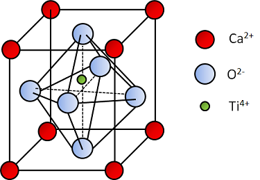
A perovskite unit cell showing the off-centered titanium ion.
A typical noncentrosymmetric crystal structure such as a perovskite (calcium titanate — CaTiO3) has a net nonzero charge in each unit cell of the crystal. However, as a result of the titanium ion sitting slightly off-center inside the unit cell, an electrical polarity develops, thereby turning the unit cell effectively into an electric dipole. A mechanical stress on the crystal further shifts the position of the titanium ion, thus changing the polarization strength of the crystal. This is the source of the direct effect. When the crystal is subjected to an electric field, it also results in a relative shift in the position of the titanium ion, leading to the distortion of the unit cell and making it more (or less) tetragonal. This is the source of the inverse effect.
Why Do We Pole a Piezoelectric Material?
In a macroscopic crystalline structure that comprises several such unit cells, the dipoles are by default found to be randomly oriented. When the material is subjected to a mechanical stress, each dipole rotates from its original orientation toward a direction that minimizes the overall electrical and mechanical energy stored in the dipole. If all the dipoles are initially randomly oriented (i.e. a net polarization of zero), their rotation may not significantly change the macroscopic net polarization of the material, hence the piezoelectric effect exhibited will be negligible. Therefore, it is important to create an initial state in the material such that most dipoles will be more-or-less oriented in the same direction. Such an initial state can be imparted to the material by poling it. The direction along which the dipoles align is known as the poling direction.
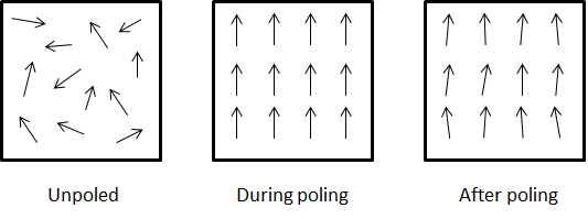
Alignment of electric dipoles represented by arrows in a material prior to poling (left), during the poling process (middle) and at the end of poling (right).
During poling, the material is subjected to a very high electric field that orients all the dipoles in the direction of the field. Upon switching off the electric field, most dipoles do not return back to their original orientation as a result of the pinning effect produced by microscopic defects in the crystalline lattice. This gives us a material comprising numerous microscopic dipoles that are roughly oriented in the same direction. It is noteworthy that the material can be de-poled if it is subjected to a very high electric field oriented opposite to the poling direction or is exposed to a temperature higher than the Curie temperature of the material.
Working with Anisotropic Material Properties
So we see that the piezoelectric effect arises inherently out of anisotropy in the crystal structure as well as poling. This also means that piezoelectric material properties such as the stiffness (or compliance) matrix, coupling matrix, and permittivity matrix are defined in a certain crystal coordinate system that is typically denoted by the 123 axes.
Conventionally, the poling direction is considered to be the 3rd axis, except in quartz where the polarity is considered to be along the 1st axis. Hence, we need to interpret the material properties in terms of these principal directions. For example, the coupling coefficient d31 indicates how much the material will strain along its 1st principal direction when an electric field is applied across the 3rd principal direction. This also means that the material properties can be used without any alteration only if the crystal’s principal directions are aligned with the coordinate system used to describe the material’s position in our simulations.
In COMSOL Multiphysics, the material’s position is specified by the Material Coordinate System, which is denoted by the (uppercase) XYZ axes. Therefore, while simulating piezoelectric materials, it is of utmost importance to take its spatial orientation and poling direction into account in order to correctly interpret the material properties. In situations where the principal axes of the crystal do not align with the axes of the Material Coordinate System, you would want to create an appropriate user-defined coordinate system to provide a mapping function for appropriate transformation (and interpretation) of the material properties. Now let’s look at a few ways of implementing this idea in COMSOL Multiphysics.
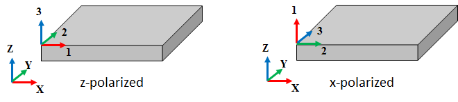
Pictorial representation of a z-poled piezo (left) where the principal crystal directions 123 are aligned with XYZ axes of the material coordinate system. An x-poled piezo (right) is represented differently such that the 1st principal direction is aligned with the Z-axis of the material coordinate system.
Using a Rotated Coordinate System
The Rotated Coordinate System in COMSOL Multiphysics allows you to specify the orientation using the Z-X-Z convention of Euler angles. This option can be particularly helpful if the orientation of the piezoelectric material or its poling direction can be expressed in terms of one or more rotations about the default rectangular coordinate system.
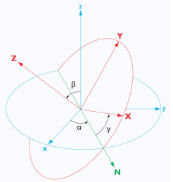
Pictorial representation of Euler angles α, β, and γ where xyz represents the original coordinate system and XYZ represents the rotated coordinate system.
For example, the Tonpilz Piezo Transducer tutorial model shows how to set up a rotated coordinate system to model the poling direction to be aligned with the negative Z-direction. This is achieved by setting the Euler angle β as 180°. Another tutorial that shows how to model a Thickness Shear Quartz Oscillator illustrates how an Euler angle of β = – 54.75° is used to represent an AT-cut quartz where the thickness of the quartz disk is oriented along the Z-direction in the COMSOL software.
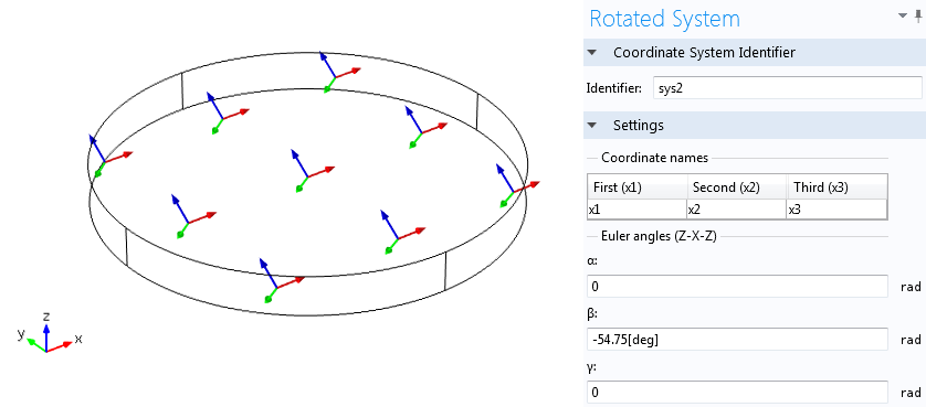
The disk represents an AT-cut quartz where the 1st principal direction is shown with blue arrows. The thickness of the quartz disk is along the software’s Z-direction. The default coordinate system is shown on the bottom-left corner. The Euler angles used to create the rotated coordinate system are shown on the right.
In the above example, if the thickness direction of the quartz disk is oriented along the Y-direction in COMSOL Multiphysics, then the same AT-cut would need to be represented by an Euler angle of β = 35.25°. Here it is worth noting that the term AT-cut does not provide absolute information about the spatial orientation of the quartz crystal in 3 dimensions.
Instead, it describes the orientation of the crystal with respect to the direction in which the disc has its thickness. If the disc is rotated in the COMSOL’s global coordinate system, a different set of Euler angles must be used, because COMSOL Multiphysics uses the rotated system to define the orientation of the crystal with respect to the global system.
In the particular case of quartz, it is also important to understand whether the material is polarized in a right-handed or left-handed sense, and also which of the two commonly utilized standards is being employed for the material properties (often quartz material properties and crystal cuts are described using the older IRE 1949 standard as opposed to the IEEE 1978 standard that is commonly used for most piezoelectric materials).
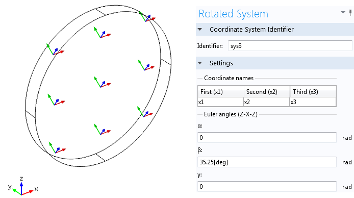
The disk represents an AT-cut quartz where the 1st principal direction is shown with blue arrows. The thickness of the quartz disk is along the COMSOL’s Y-direction. The default coordinate system is shown on the bottom-left corner. The Euler angles used to create the rotated coordinate system is shown on the right.
Note: In version 4.4.0.195 (COMSOL 4.4 with Update 1), COMSOL Multiphysics has introduced four options for material properties of quartz to choose from. These are, respectively, the material properties as described by the 1949 IRE Standard and 1978 IEEE Standard with both left-handed and right-handed polarizations. The signs (positive and negative) for some of the material properties (such as c14, d11, etc.) differ depending on which system is used to define the material properties. Additional details on this topic are available in the documentation of an updated version of the Model Library example Thickness Shear Quartz Oscillator.
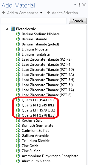
Piezoelectric materials available in COMSOL Multiphysics. The material properties of quartz are available in both the 1949 IRE Standard and 1978 IEEE Standard formats for left-handed as well as right-handed polarized quartz.
Using a Base Vector Coordinate System
An alternate option would be to specify a set of vectors that relate the crystal coordinate system with the material coordinate system. This option, known as the Base Vector Coordinate System in COMSOL, allows you to create orthogonal or even non-orthogonal coordinate systems. For example, the tutorial model of a piezoelectric shear-actuated beam shows how to implement a poling direction that reflects a rotation of the material by 90º about the Y-axis by specifying appropriate base vectors.
A more advanced usage of the same feature would allow you to create a radially polarized (in cylindrical coordinates) piezoelectric disk or a radially polarized (in spherical coordinates) hollow piezoelectric shell.
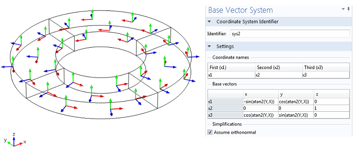
The disk represents a radially polarized PZT-5H where the 3rd principal direction (poling direction) is shown with blue arrows. The default coordinate system is shown on the bottom-left corner. The base vectors used to create the cylindrical coordinate system are shown on the right.
There are also other options of creating user-defined coordinate systems in the COMSOL simulation software that you could use. For instance, you could create a curvilinear coordinate system for working with an anisotropic material that is arbitrarily curved in space. You can find more information on this feature in one of our past blog entries.
Additional Resources
- If you are interested in more information on modeling piezoelectric devices using COMSOL Multiphysics, watch our archived webinar on piezoelectric simulations.
- A tutorial video on modeling a piezoelectric Tonpilz transducer is also available on our Video Center to show you how to implement opposite poling directions in alternate piezo layers in a piezo-stack actuator.
- For more technical details on piezoelectric simulations and working with user-defined coordinate systems, you can refer to the COMSOL Multiphysics Reference Manual, Acoustics Module Users Guide, MEMS Module Users Guide, and Structural Mechanics Module Users Guide.


Comments (0)