
With shrinking electronic devices and ever-increasing power densities, efficient thermal management is at the heart of many R&D activities for electronics engineers. When developing complete systems containing multiple components, designs can become rather complex. An example of such a design would be a computer power supply unit (PSU), which can include not only electronics, but also multiple heat sinks, cooling fans, perforated grilles, and other large components — all within a small enclosure. In this blog post, we will explore some of the dedicated features available in the Heat Transfer Module for modeling such electronics cooling systems.
Modeling a Forced Convection Cooling System
A forced convection cooling system, such as a PSU, is used for removing excess heat produced by electrical computer components. Although these components are designed to produce as little heat as possible, the decreasing size of many electronic devices continually confine heat dissipation systems to ever-smaller spaces, resulting in the need for well planned and optimized designs. Failure to adequately dissipate heat in a computer can lead to temporary malfunctions or even permanent failure if integrated circuits, disk drives, central processing units (CPUs), or other components overheat.
Power supply units contain a cooling system to actively reduce the temperature of a device by exhausting hot air. An example of a PSU geometry, available for download from the Model Gallery, is shown below. The geometry contains an extracting fan as well as a perforated grill to direct the laminar airflow within the enclosure. A printed circuit board (PCB) is represented along the bottom of the box by an anisotropic material with a thermal conductivity along the x-, y-, and z-axes of 10, 10, and 0.36W/m/K, respectively.
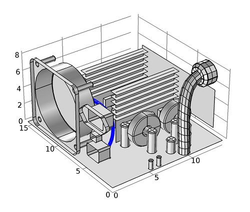
As you can see, the model geometry is quite intricate and requires a fine mesh in order to solve accurately. Modeling a lot of detail can lead to large computational costs, but the Heat Transfer Module (or alternatively the CFD Module, both add-on products to COMSOL Multiphysics) offers dedicated features to overcome this so you can effectively model the PSU cooling system components. In the example shown here, the PCB, inductor surfaces, heat sink, and enclosure are all modeled using the Highly Conductive Layer feature. This feature is specifically designed for simulating thin geometries and shortens computation time and reduces memory consumption by reducing the number of degrees of freedom within the model. Additionally, the fan can be modeled using the Fan boundary condition, also available with the Heat Transfer Module and the CFD Module. Data on the fan curve (static pressure vs flow rate), usually provided by the manufacturer, can be added to configure the boundary condition.
PSU Cooling: Which Components Are Overheating?
The inlet air temperature, which would come from within the computer case, is set at 30°C to reflect the heat already dissipated from other components. Below you can see a table of the components and their assigned heat sources:
| Components | Total Power (W) |
|---|---|
| Transistor cores | 25 |
| Big transformer coil | 5 |
| Small transformer coils | 3 |
| Inductors | 2 |
| Large capacitors | 2 |
| Medium capacitors | 3 |
| Small capacitors | 1 |
The PSU consumes a maximum of 230 W, and the overall heat loss is 41 W, demonstrating an efficiency rate of about 82%. By running an analysis on the system, we can determine where the maximum temperature is within the device, as shown below:
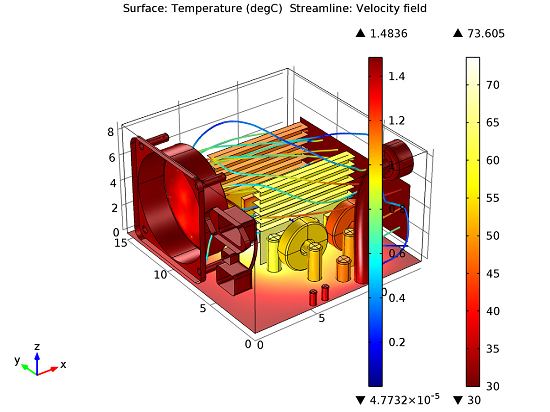
Plot of the temperature and fluid velocity fields within the enclosure.
The analysis shows that there is a heterogeneous distribution of temperature within the enclosure, as a result of the combination of heat dissipation due to active components (see table above) and the air cooling induced by the fan. The maximum temperature (74°C) is found at one of the transistor cores, which makes sense since we noted in the table above that the dissipated power is largest in the transistor component. The plot above also shows that the PCB helps to distribute heat within the enclosure. The air flow has also been computed, and the manner in which it flows around obstacles is depicted by streamlines.
Model Download
- Download the model from the Model Gallery: Forced Convection Cooling of an Enclosure with Fan and Grille


Comments (0)